google-site-verification: google0228a1feb97d321e.html
google-site-verification: google0228a1feb97d321e.html
google-site-verification: google0228a1feb97d321e.html
google-site-verification: google0228a1feb97d321e.html
google-site-verification: google0228a1feb97d321e.html
google-site-verification: google0228a1feb97d321e.html
Understanding the structure and power generation principle of perovskite - ultrasonic spraying
Perovskite solar cells are considered to be the third generation of photovoltaic power generation technology that will replace silicon-based solar energy due to their simple process, extremely high potential efficiency and extremely low material cost.
1. Perovskite solar cells
Similar to crystalline silicon cells, perovskite solar cells also have different "layers" stacked together, and each layer has its own special functions and effects.
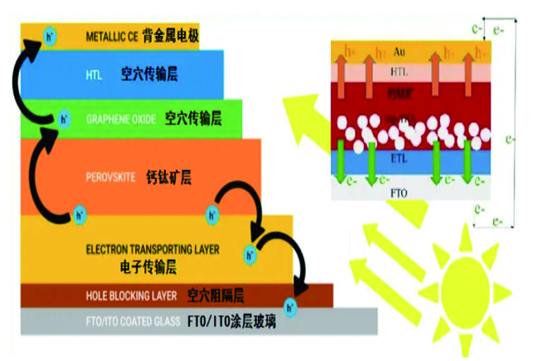
The cell prototype in the figure includes an n-type dense layer, a mesoporous oxide layer, a light-harvesting perovskite layer, a hole transport layer, and two electrodes. The general structure of the PSC and the different layers are deposited step by step as indicated.
①: Fluorine-doped tin oxide (FTO)/indium-doped tin oxide (ITO) coated glass is used as the substrate for the photoanode of the perovskite device, and the flexible substrate is usually ITO/PEN.
②: Above it, there is a layer of dense semiconductor material, mainly TiO₂, which acts as a hole blocking layer or dense layer, usually deposited on top of the FTO substrate by ultrasonic spraying. It prevents the holes extracted by the electron selective layer above from contacting the FTO/ITO glass and suppresses recombination losses.
③: Next comes the ETL, which promotes the diffusion of electrons from the photoexcited perovskite layer into the FTO/ITO glass and thus to the external circuit.
④: The perovskite layer can act as a sensitizer or absorber or electron or hole transporter, although its main function is a sensitizer, but it is sprayed on the electron transport layer.
⑤: Adjacent to the perovskite layer is the hole transport layer, which allows the holes in the excited perovskite to move to the metal cathode for extraction. The graphene structure makes the hole transport more efficient.
⑥: Finally, there is a metal contact layer, which is usually deposited on the top of the solar cell by thermal evaporation and serves as a counter electrode, also known as the back contact.
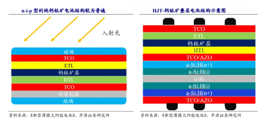
For practical perovskite components, the above perovskite solar cells need to be further encapsulated. Similar to crystalline silicon components, encapsulation film and cover glass are required.
2. General working principle of perovskite solar cells:
The perovskite layer absorbs sunlight and the energy in the photons is used to excite electrons. This absorption manifests as electrons being excited from the valence band edge (or highest occupied molecular orbital, HOMO) of the perovskite sensitizer to its conduction band edge (or lowest unoccupied molecular orbital LUMO), leaving the perovskite in an oxidized state, i.e., neutralized by electrons moving from the HOMO of the adjacent hole transport layer.
The electrons excited to the LUMO of the perovskite are then injected into the LUMO of the ETL and transported to the front contact by diffusion. The energy levels are thermodynamically aligned in such a way that when an electron from the valence band edge of the perovskite is excited to the conduction band edge, it leaves a hole in the perovskite, which another electron from the HOMO of the HTL can then fill in.
Thus, the current is generated by the hopping motion of electrons and holes. The HTL allows the holes extracted from the perovskite layer to pass through and extracts them to the external circuit. The HTL also acts as an electron blocking layer and prevents any electrons from passing through.
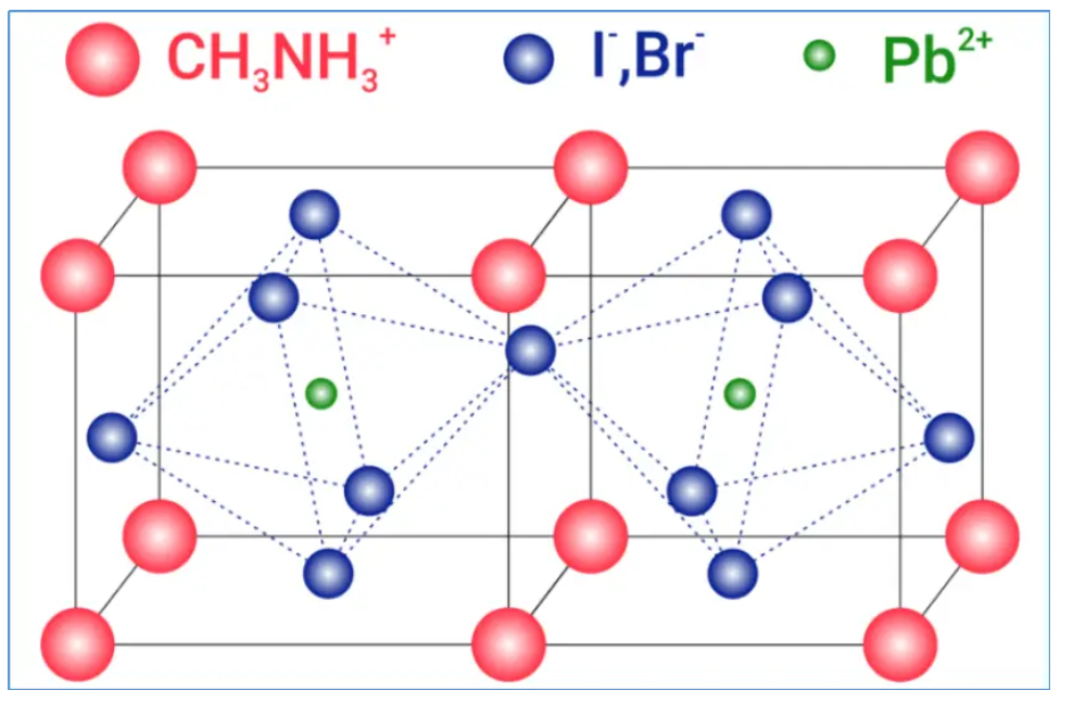
Although perovskite materials have shown promising results in terms of improving efficiency, they do have some disadvantages that hinder their commercialization. They possess organic cation formation and are therefore susceptible to moisture, temperature, UV radiation, and oxygen, which can degrade the performance of solar cells in a short period of time, with maximum stability values reported to be just over 1000 hours.
3. Advantages of ultrasonic spray deposition coating:
1. Ultrasonic spray technology is easy to operate, has a fast preparation process, and can adapt to substrates of different sizes and shapes. Compared with other coating technologies, ultrasonic spraying can achieve uniform coating over a large area, improve production efficiency and process stability.
2. By controlling the ultrasonic spraying process parameters, the thickness of thin film deposition can be achieved. This is very important because the thickness of the coating directly affects the charging and discharging performance of solar cells.
3. Ultrasonic spraying technology does not require expensive equipment and complex processes, and has a high utilization rate of glass materials. This can reduce production costs and improve the competitiveness of perovskites.